The Role of CAD Software in Custom Sheet Metal Fabrication: A Comprehensive Guide
Custom sheet metal fabrication is a cornerstone of modern manufacturing, playing a vital role across industries such as aerospace, automotive, electronics, construction, and consumer goods. As design complexity increases and precision becomes critical, manufacturers rely heavily on advanced technologies to meet these demands. One such transformative technology is Computer-Aided Design (CAD) software. CAD software enables engineers and fabricators to create, visualize, and optimize custom sheet metal fabrication components digitally before actual production, significantly enhancing efficiency, accuracy, and flexibility in the fabrication process.
In this comprehensive guide, we will explore the pivotal role of CAD software in custom sheet metal fabrication, discussing its capabilities, advantages, integration with manufacturing processes, and future trends shaping the industry.
Introduction to Custom Sheet Metal Fabrication
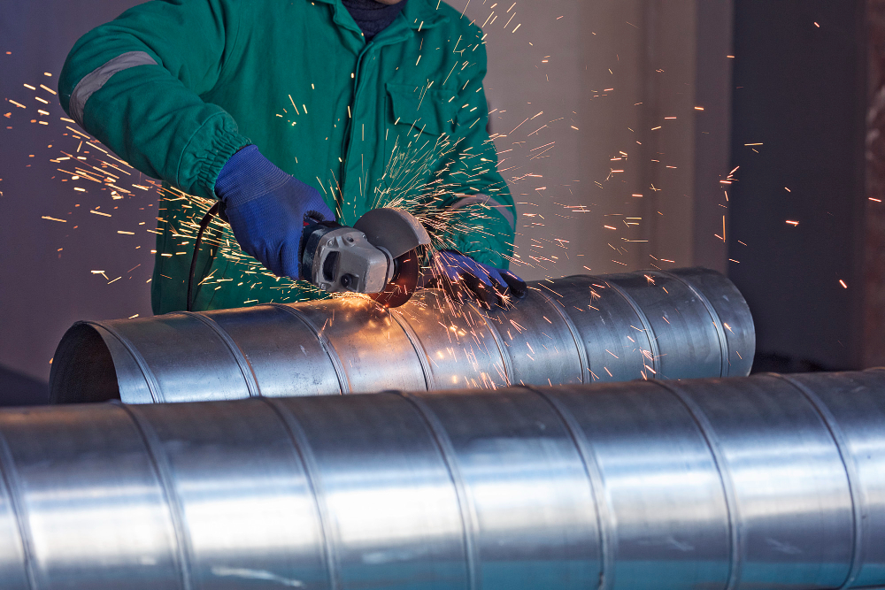
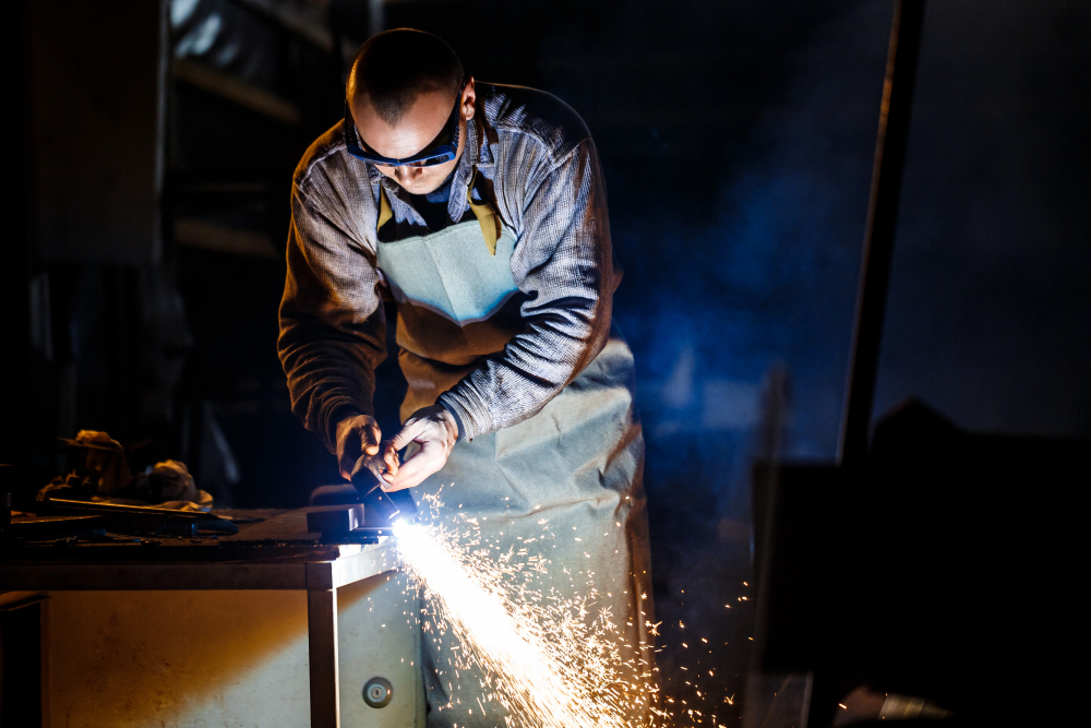
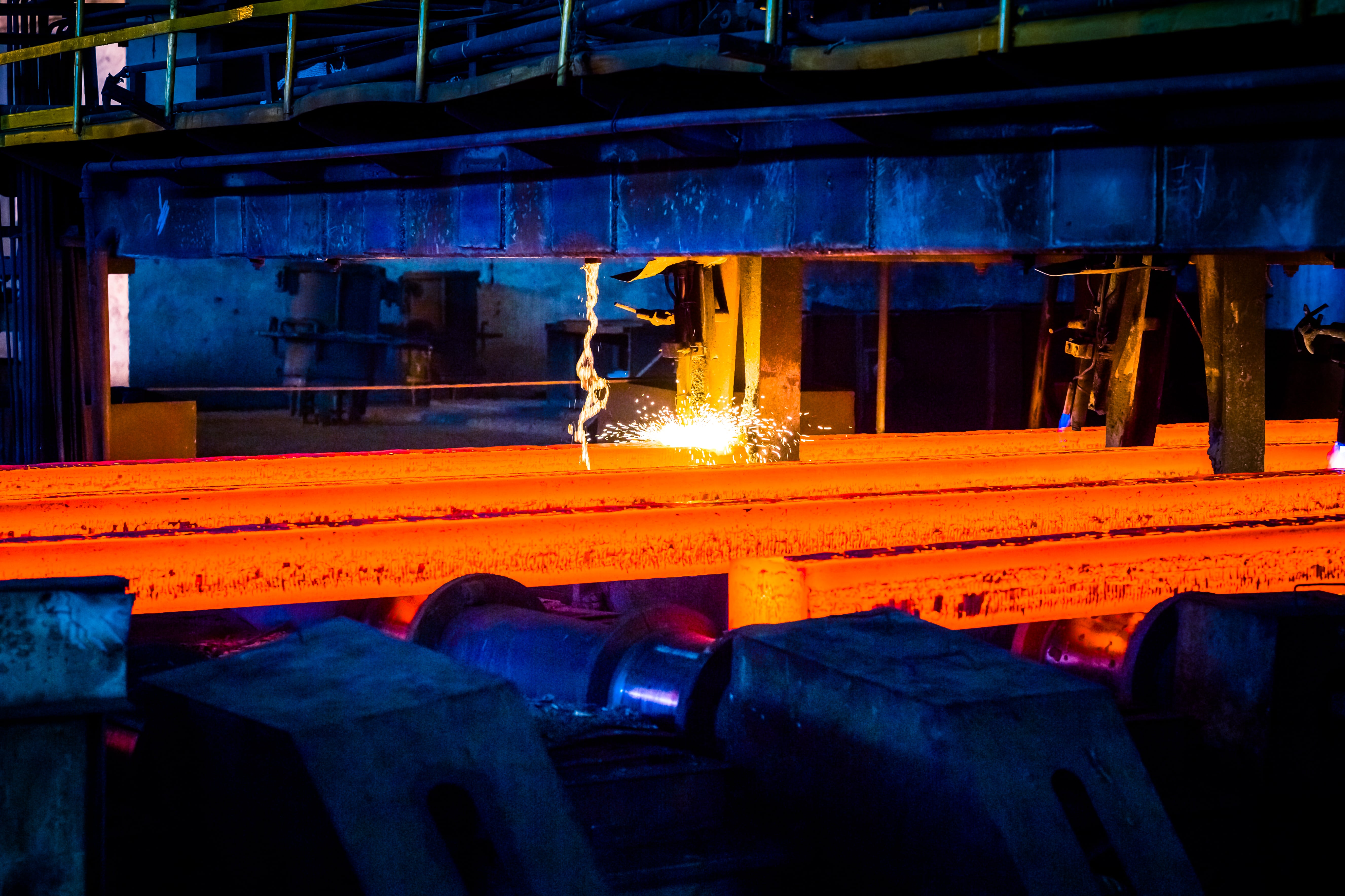
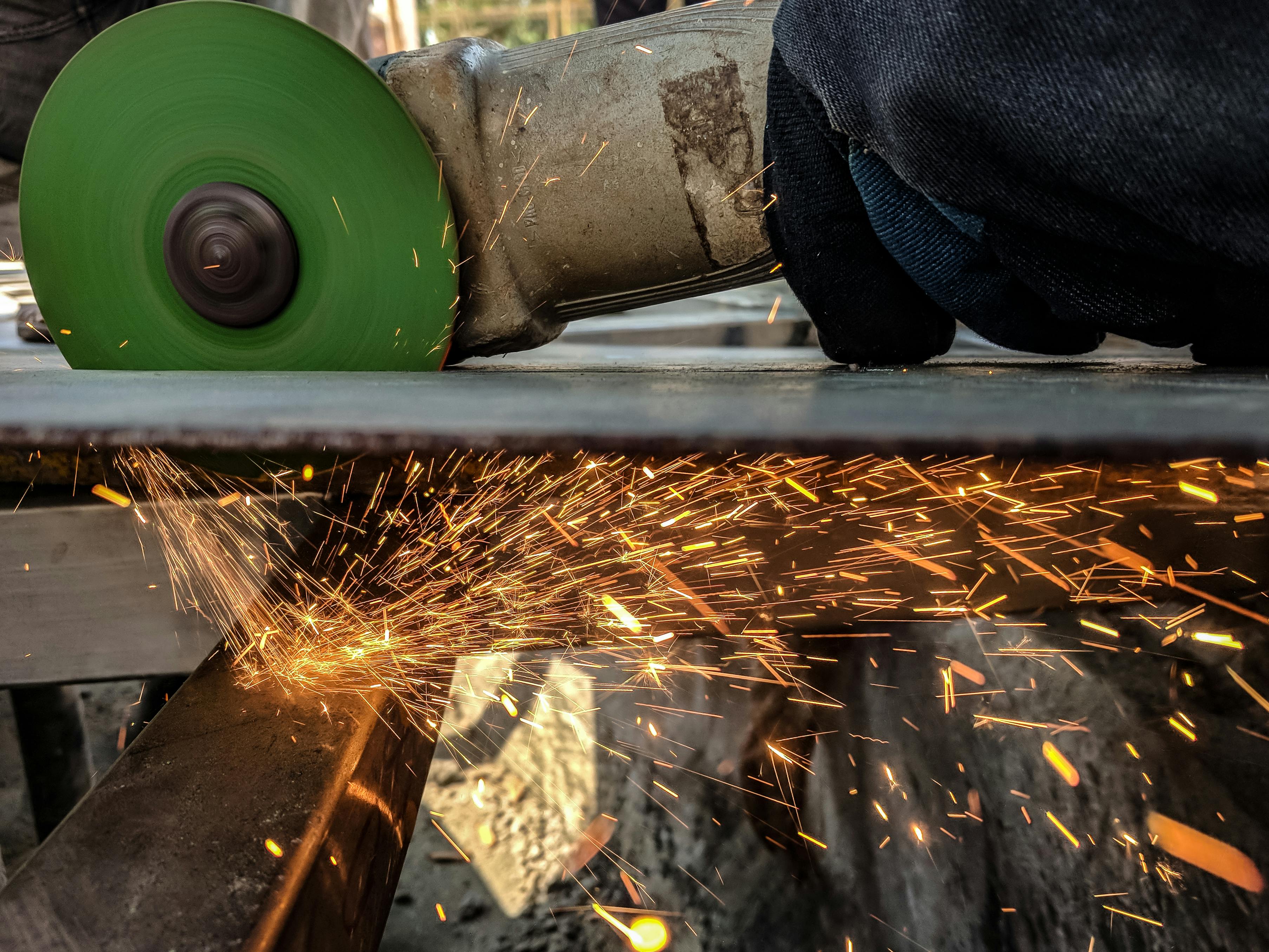
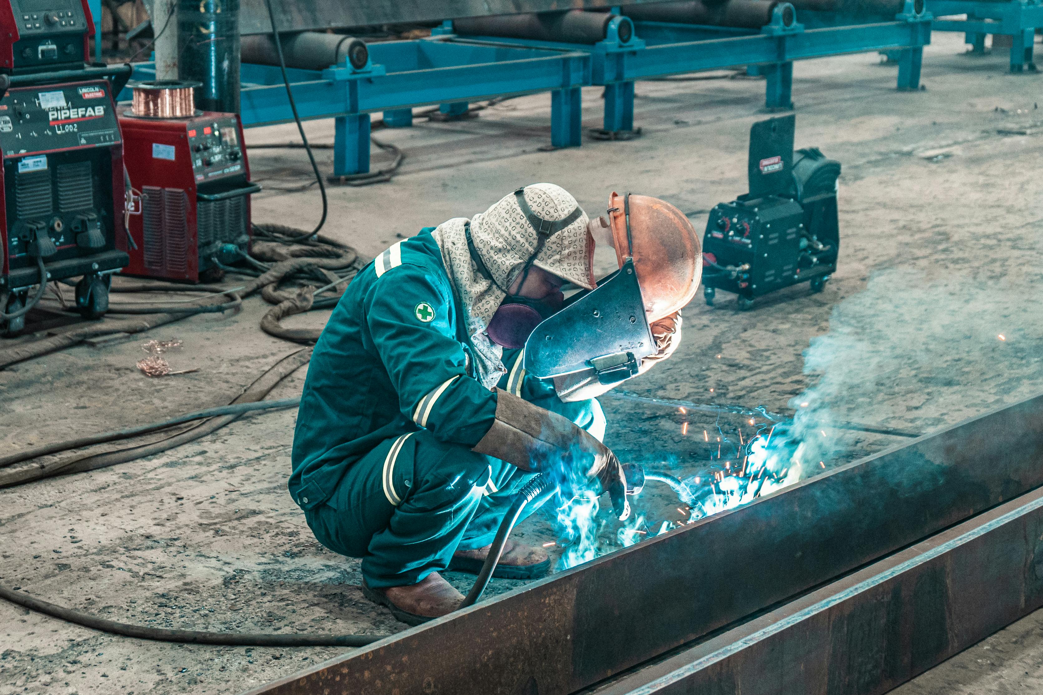
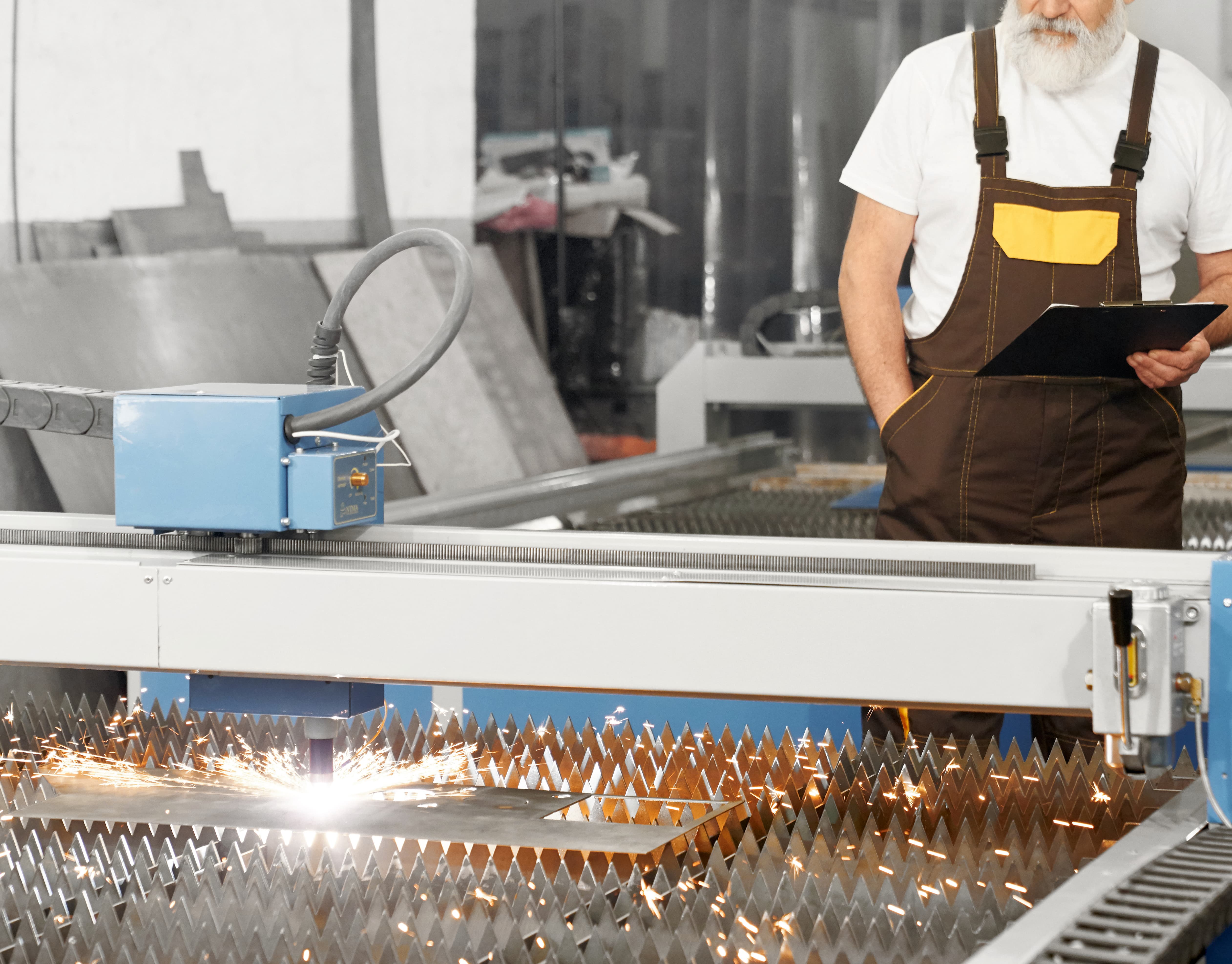
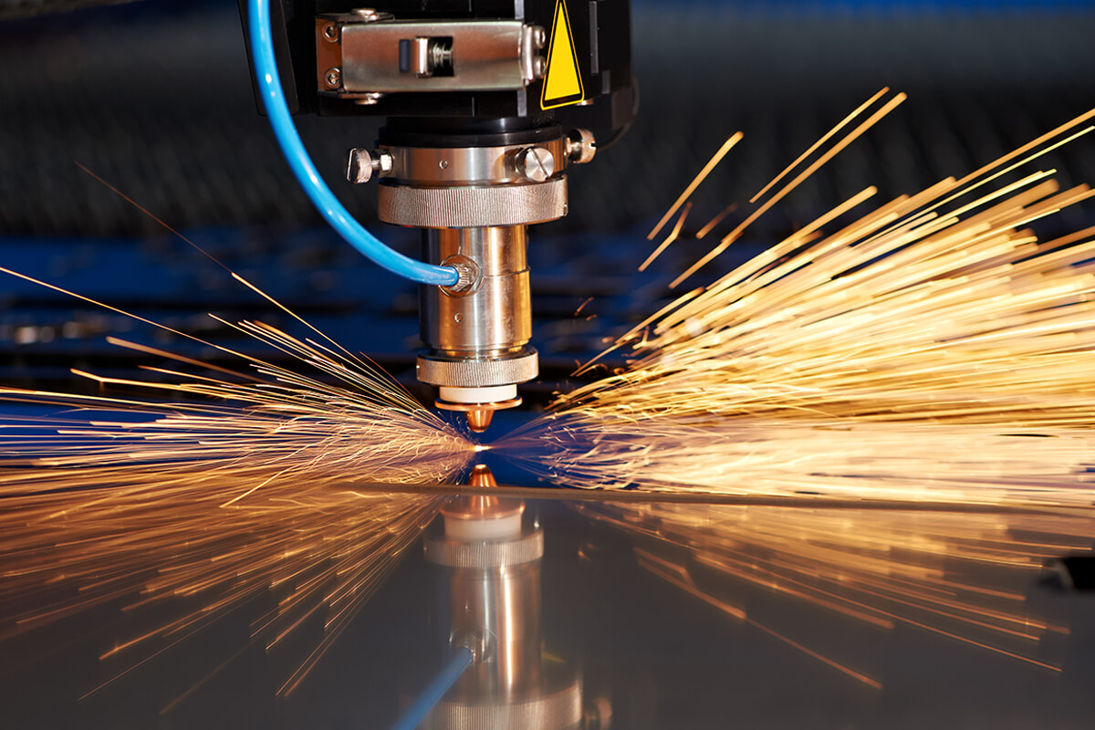
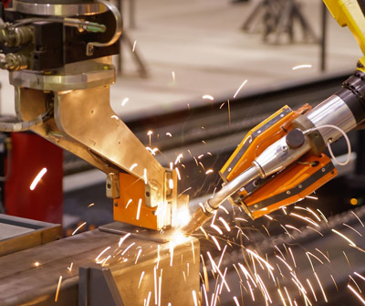
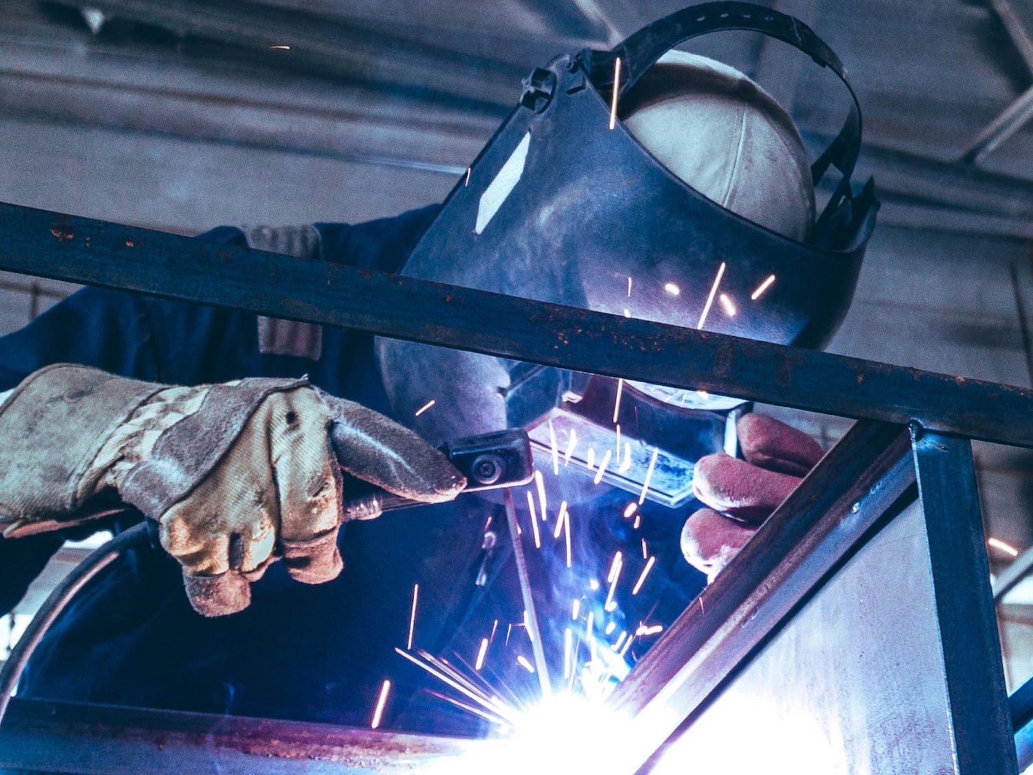
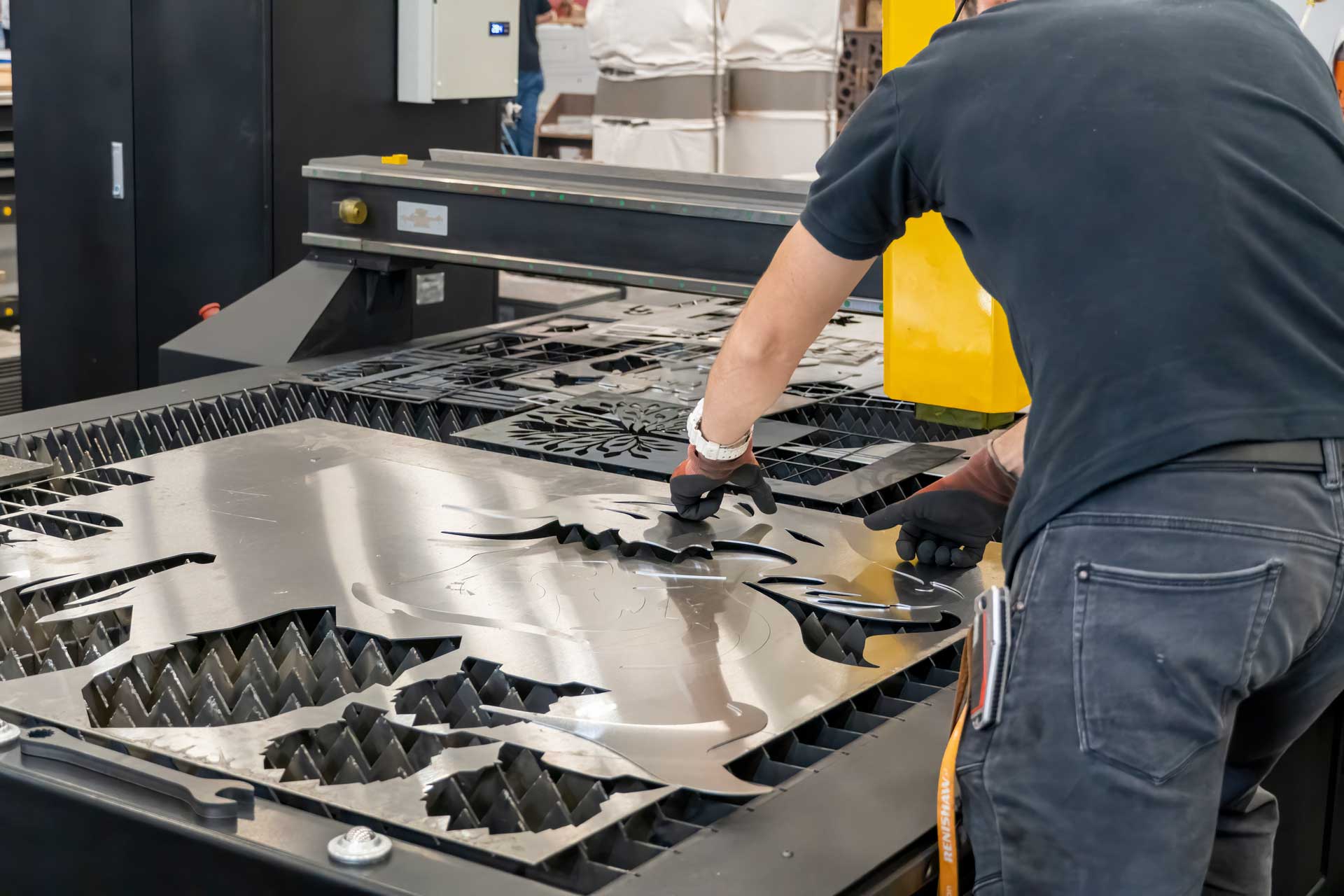
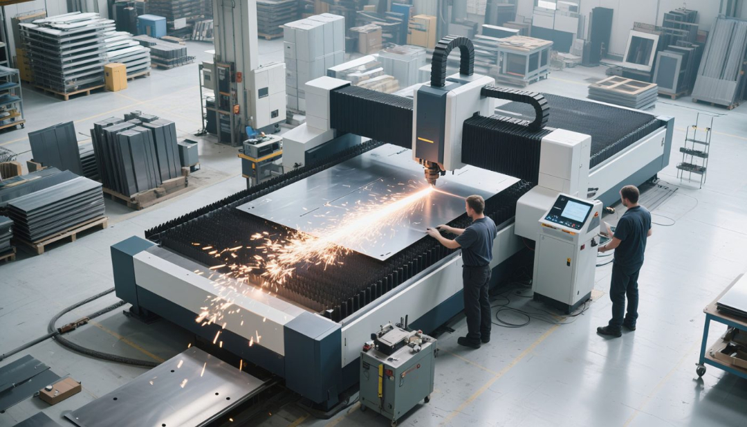
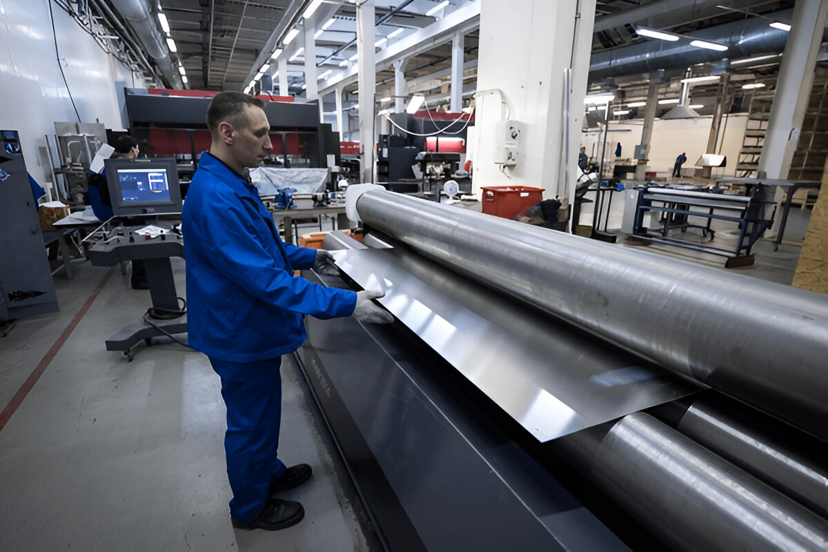
Sheet metal fabrication involves cutting, bending, and assembling thin metal sheets into parts and components that form the backbone of countless products. Custom fabrication refers to creating unique parts tailored to specific design requirements, often with tight tolerances and complex geometries.
Historically, sheet metal fabrication was manual, relying on hand sketches, physical prototypes, and traditional tools, which were time-consuming and prone to error. Today, the landscape has dramatically shifted with digital technologies—especially CAD software—enabling manufacturers to design intricate parts with unmatched precision and speed.
Understanding CAD Software
Computer-Aided Design (CAD) software provides a digital environment where designers can create precise 2D drawings and 3D models of components. Unlike manual drafting, CAD software offers tools for parametric design, simulation, and automated documentation.
In the context of sheet metal fabrication, CAD software often includes specialized modules that handle the unique requirements of sheet metal parts, such as bend allowances, relief cuts, and flat pattern unfolding.
Commonly used CAD platforms in the sheet metal industry include:
- AutoCAD (Autodesk)
- SolidWorks (Dassault Systèmes)
- Autodesk Inventor
- CATIA (Dassault Systèmes)
- Siemens NX
These platforms offer powerful tools that help engineers transition smoothly from concept to manufacturing.
Why CAD Is Essential for Sheet Metal Fabrication
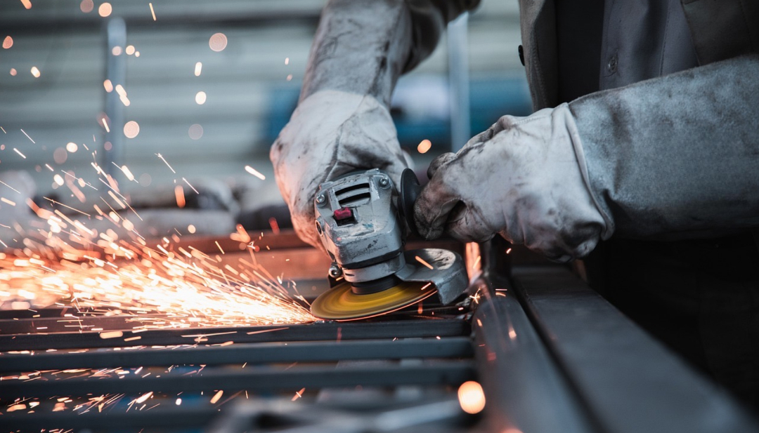
Sheet metal fabrication is a multi-step process requiring precision in every phase: design, cutting, bending, and assembly. Here’s why CAD software is vital:
Precision and Accuracy
CAD software enables exact dimensioning and feature placement, reducing errors that can arise from manual drafting.
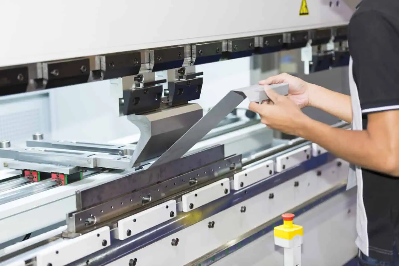
Complex Geometry Handling
Modern products often involve intricate bends, cutouts, and compound curves. CAD makes it easy to model these features and verify their manufacturability.
Simulation Capabilities
CAD software can simulate bends, stresses, and material behavior to anticipate and avoid fabrication problems.
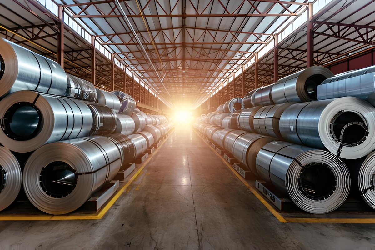
Material Optimization
By nesting flat patterns efficiently, CAD helps minimize scrap material, cutting costs.
Enhanced Documentation
Detailed fabrication drawings, bills of materials (BOMs), and instructions are generated directly from the CAD model.
Seamless Integration
CAD designs are easily transferred to CAM software and CNC machines, ensuring smooth production workflows.
Key Features of CAD Software for Sheet Metal Design
Parametric and Feature-Based Modeling
Parametric modeling means parts are defined by parameters (thickness, bend radius, flange length) that can be modified to update the entire design automatically.
Sheet Metal Specific Tools
- Bend Allowance and K-Factor: CAD calculates material stretch and compensation for bending, ensuring flat patterns fit perfectly after forming.
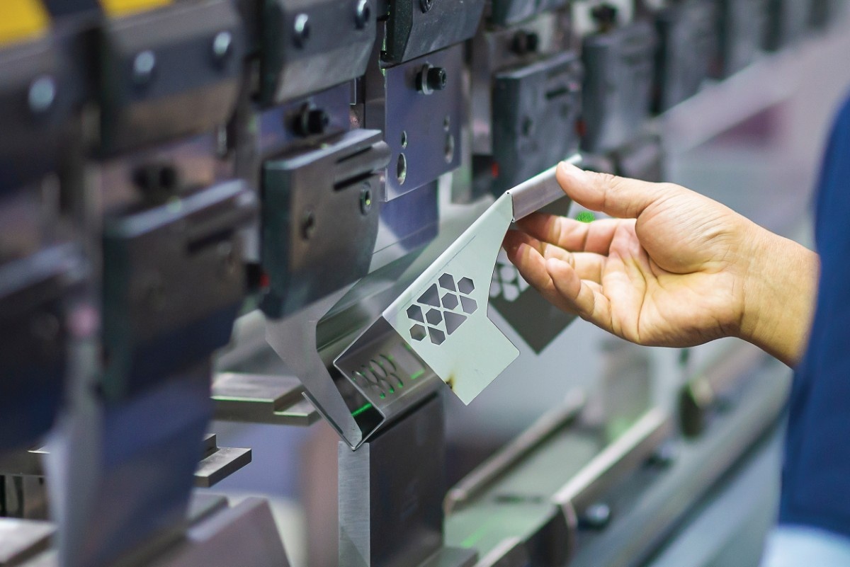
- Flanges, Hems, and Relief Cuts: Specialized tools add these common sheet metal features quickly and accurately.
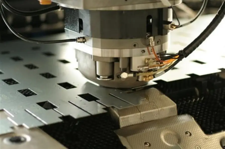
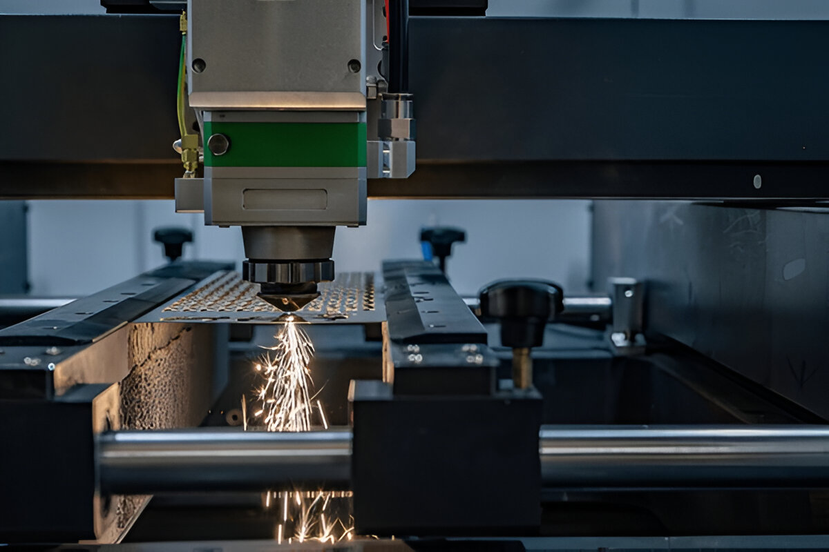
- Flat Pattern Generation: The 3D model is unfolded into a 2D flat pattern for laser cutting or punching.
- Unfolding/Refolding Simulation: Allows verification of the bending process to avoid interference and errors.
Material Libraries
CAD software comes preloaded with material properties (e.g., tensile strength, thickness), enabling realistic simulations.
Collaboration and Version Control
Modern CAD systems offer cloud-based collaboration tools that enable multiple stakeholders to work on designs simultaneously and track revisions.
The CAD-Driven Workflow in Custom Sheet Metal Fabrication
A typical CAD-driven workflow looks like this:
Design Initiation
Designers start by creating a 3D model based on customer requirements, incorporating functional and aesthetic considerations.
Iteration and Simulation
The model undergoes iterative changes, with simulations to check bending feasibility, structural integrity, and interference.
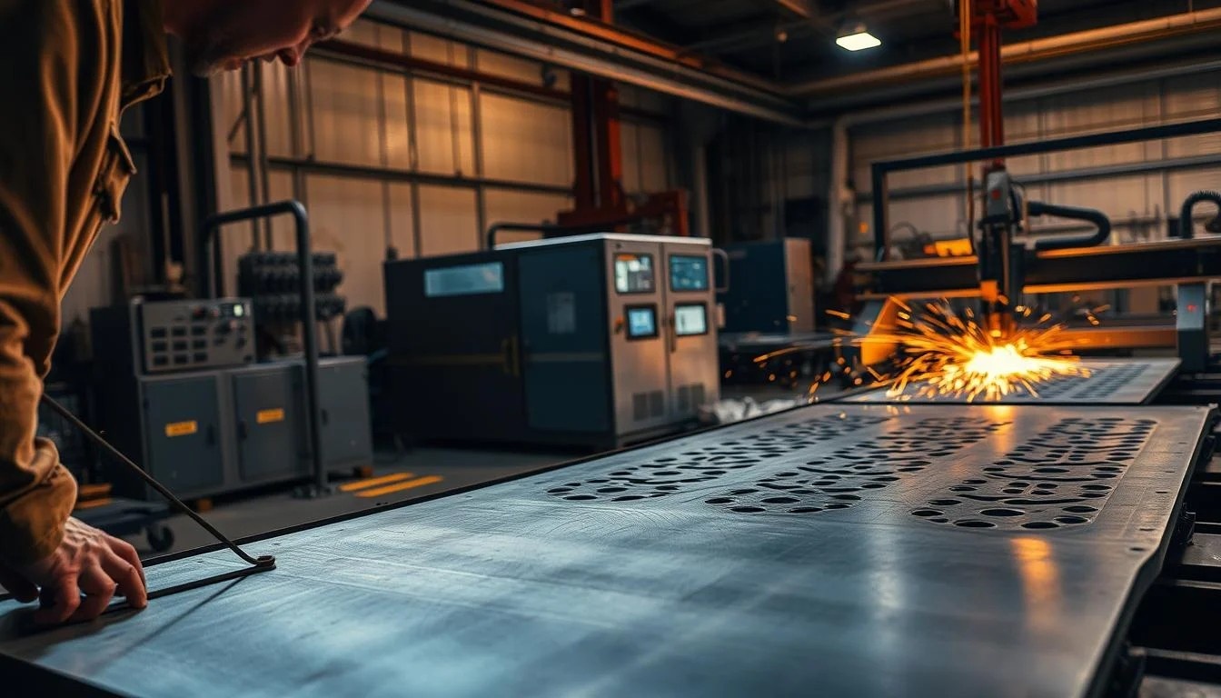
Flat Pattern Creation and Nesting
The model is flattened into a 2D layout for cutting. Nesting software arranges parts to maximize material usage on sheet metal stock.
Documentation and Export
Detailed fabrication drawings and BOMs are generated automatically. The flat patterns are exported in standard formats (DXF, DWG) for CAM use.
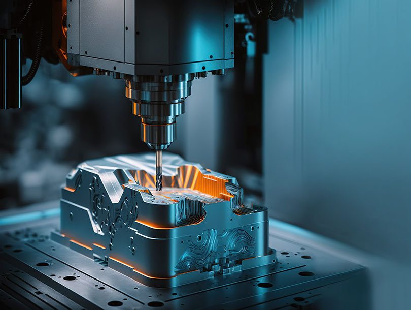
CAM Programming
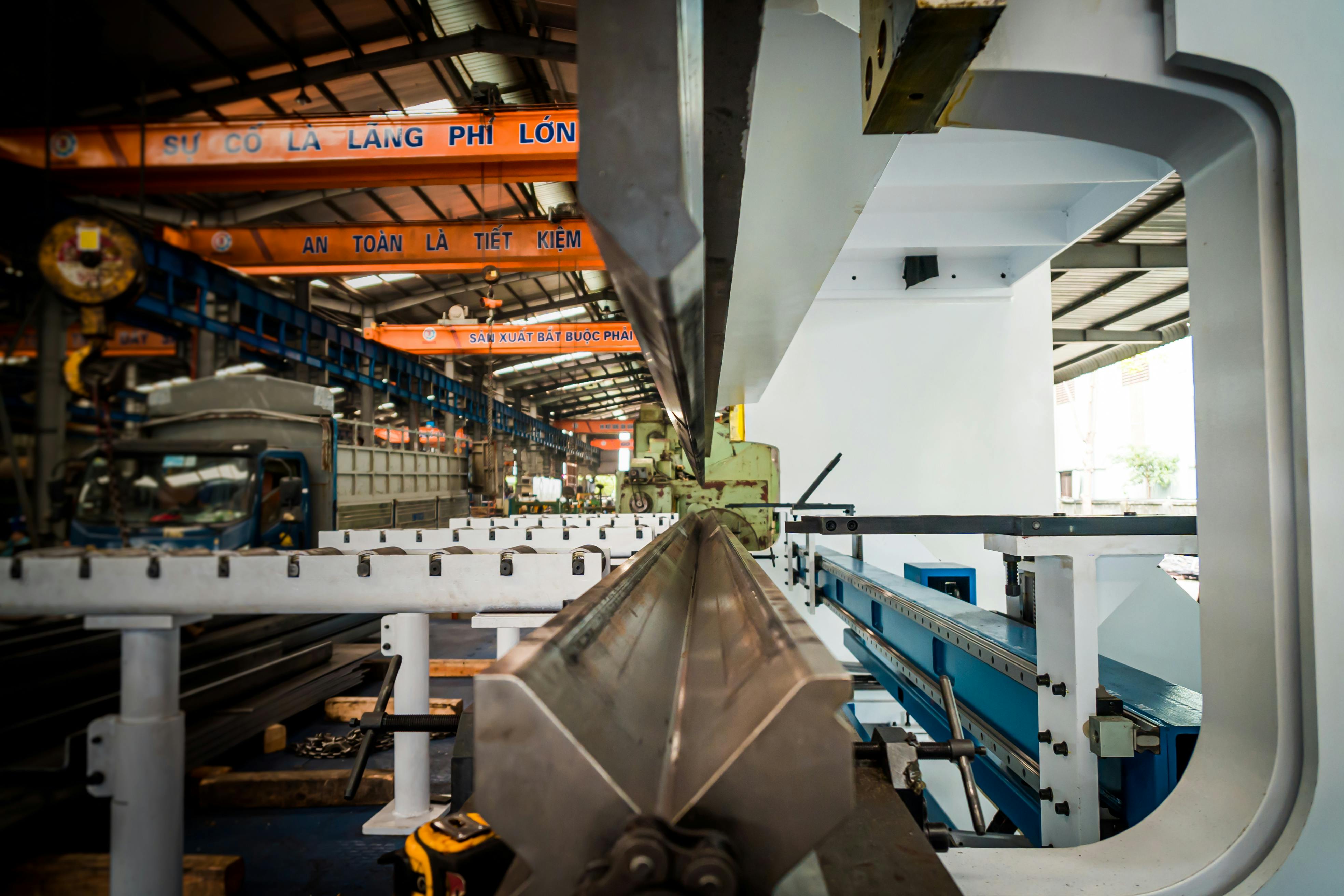
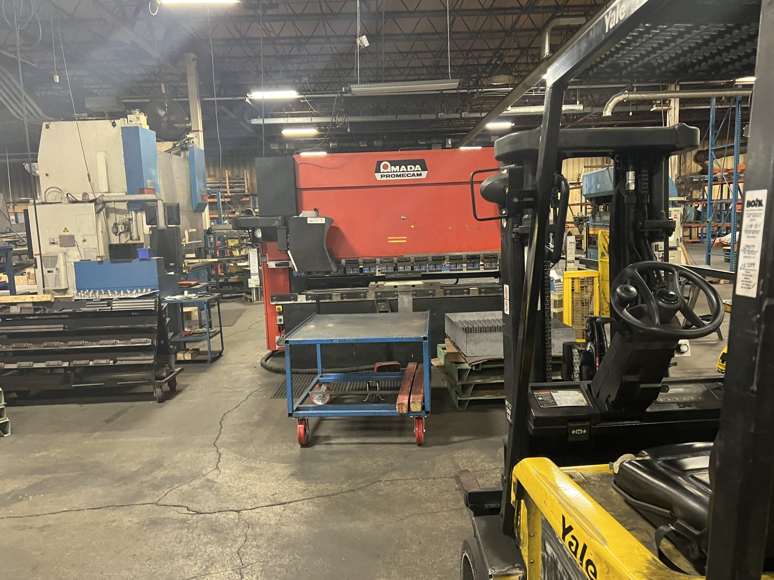
CAM software imports the CAD data and creates CNC toolpaths for laser cutters, turret punches, and press brakes.
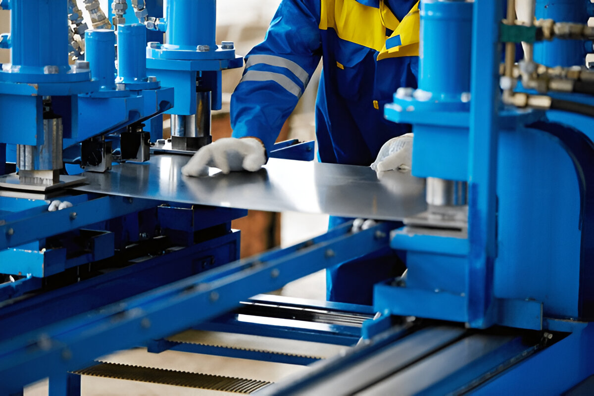
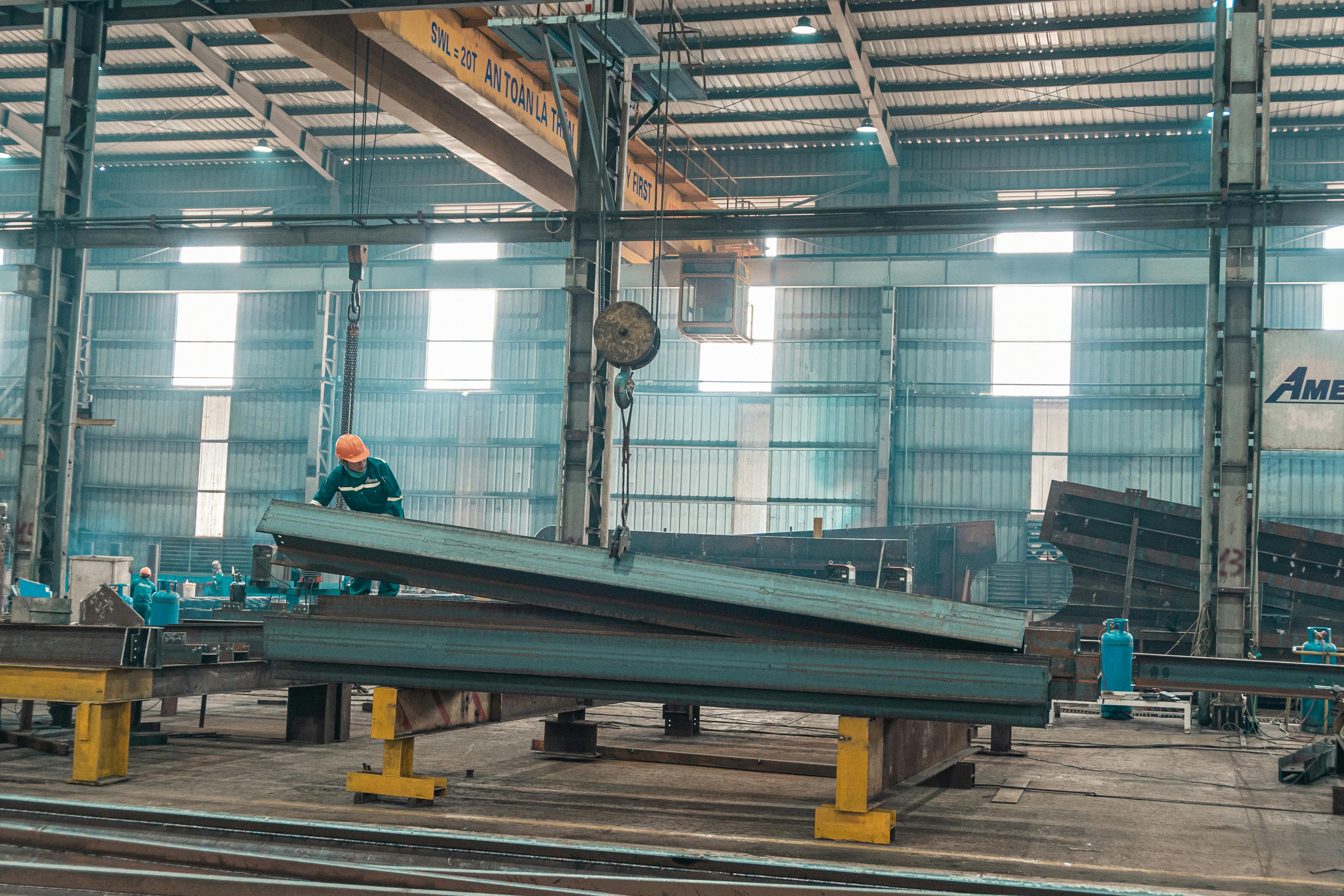
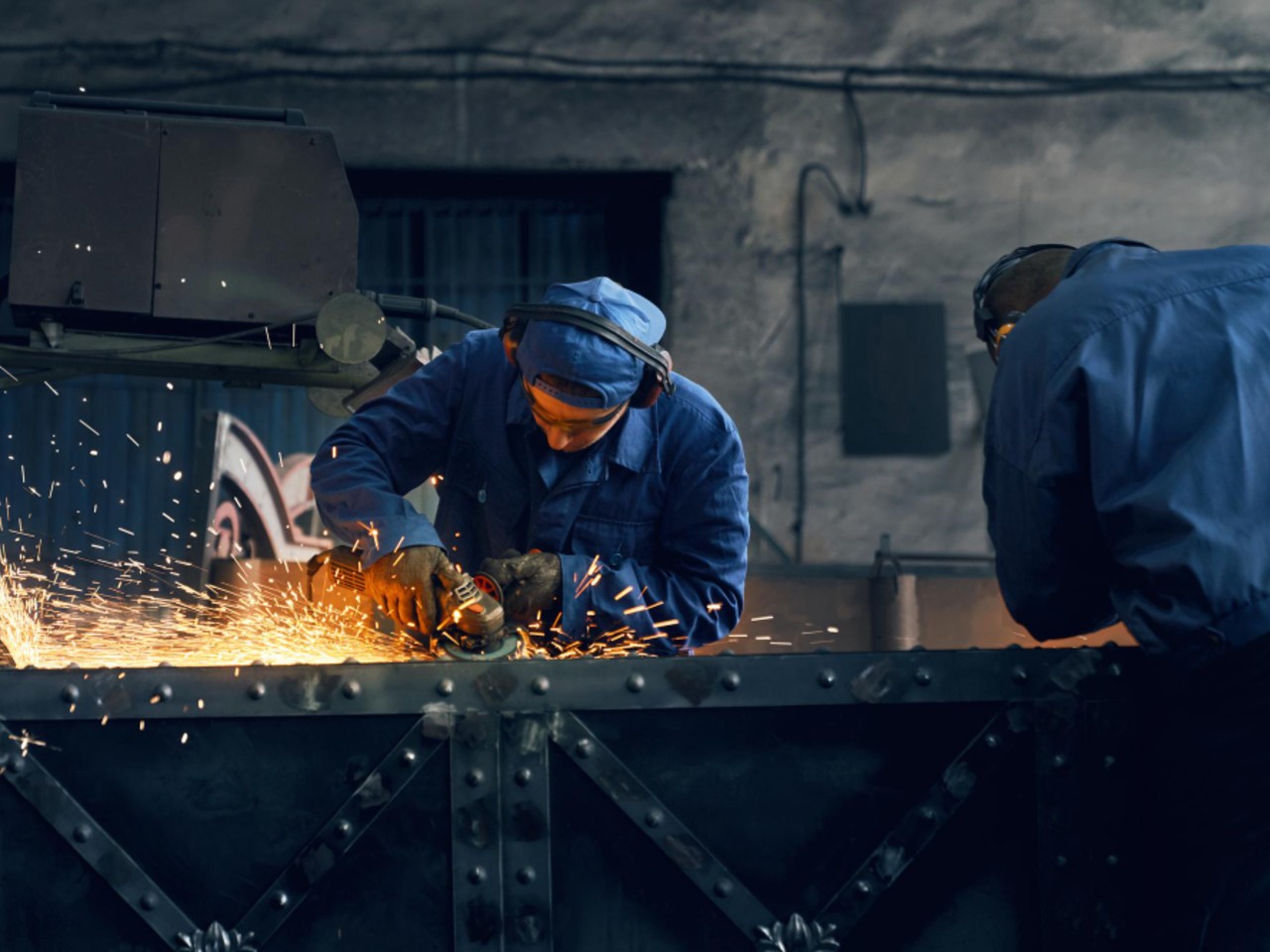
Fabrication and Assembly
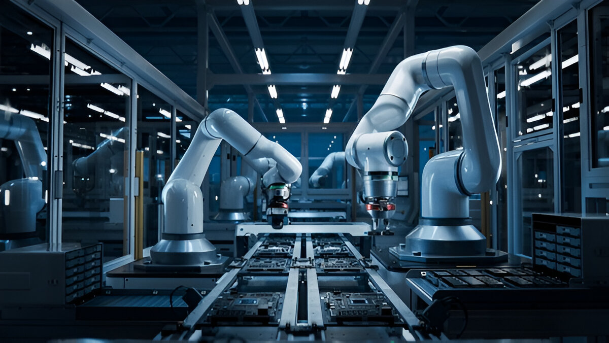
Parts are cut, bent, and assembled according to the digital instructions, with minimal manual intervention.
Quality Control
Inspection tools verify parts against the CAD model, ensuring compliance with specifications.
Integration of CAD with CAM and CNC Fabrication
The link between CAD and manufacturing is strengthened by CAM software and CNC machines:
- Direct Data Transfer: CAD designs export to CAM, which generates machine toolpaths. This digital thread eliminates data re-entry errors.
- Automated Toolpath Optimization: CAM programs optimize cutting sequences and bending orders to reduce cycle times.
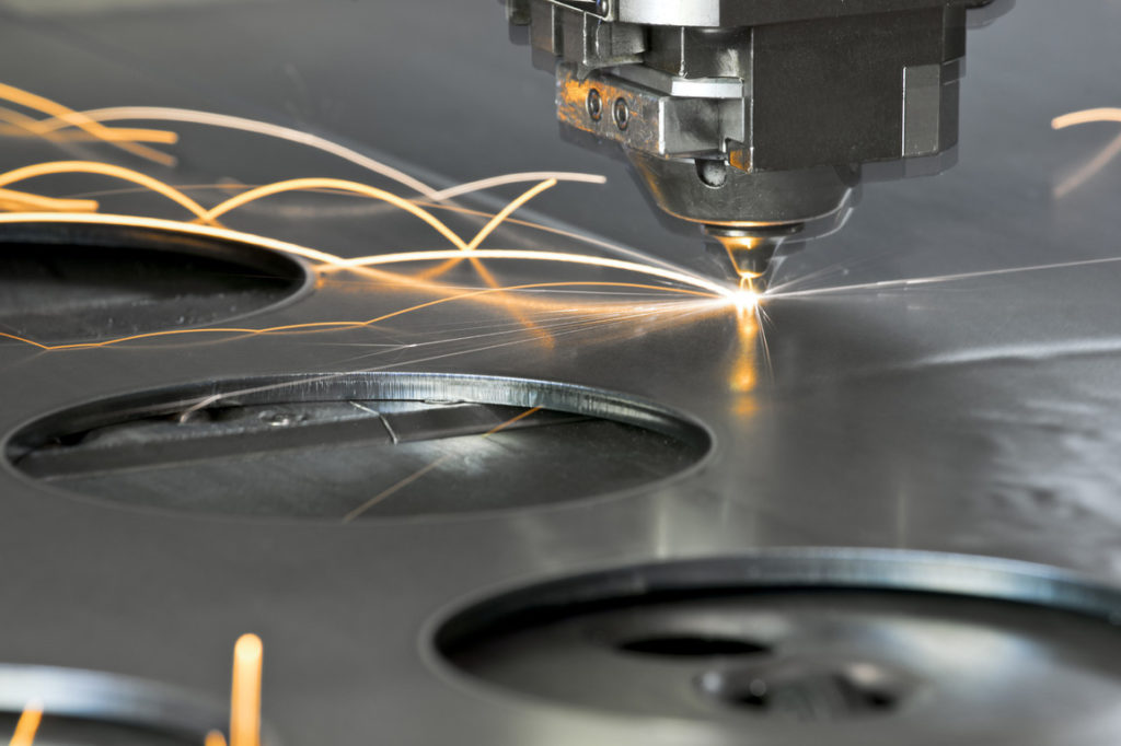
- CNC Machine Compatibility: G-code generated from CAM directs laser cutters, punch presses, and press brakes with precision.
- Real-Time Monitoring: Modern CNC machines can send feedback to CAD/CAM systems for process adjustments, reducing scrap and downtime.
Benefits of CAD Software in Custom Sheet Metal Fabrication
1. Increased Accuracy and Reduced Errors
Digital design eliminates manual measurement mistakes and misinterpretations.
2. Faster Time-to-Market
Rapid prototyping and direct CNC programming speed up production cycles.
3. Cost Efficiency
Optimized nesting and reduced scrap save material costs, while fewer physical prototypes lower expenses.
4. Enhanced Collaboration
Multiple teams (design, engineering, manufacturing) can work concurrently, reducing bottlenecks.
5. Greater Flexibility
Design changes are easily implemented without redrawing from scratch.
6. Improved Quality
Simulations and automated documentation ensure consistent output that meets specifications.
Industry Applications and Real-World Examples
Automotive Industry
CAD is used extensively to design complex body panels, brackets, and chassis parts with high precision. Simulation tools help predict spring-back and forming issues.
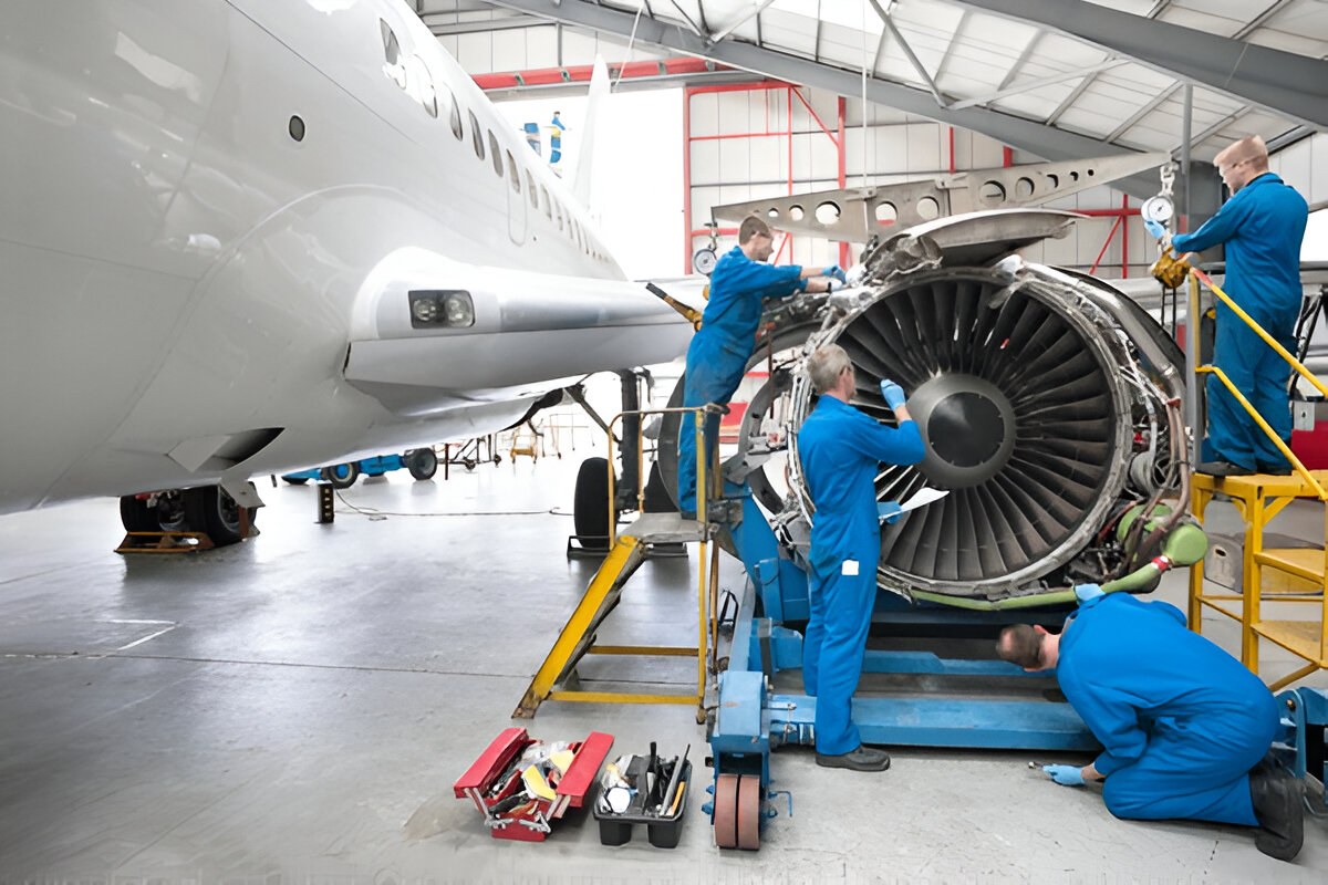
Aerospace
Lightweight, structurally sound parts such as ducting and supports are designed with CAD, meeting stringent regulatory requirements.
Electronics
Enclosures and chassis with precise cutouts and ventilation are designed to meet both functional and aesthetic demands.
Architecture and HVAC
Custom metal panels, decorative features, and ducting systems are fabricated efficiently with CAD-driven workflows.
Challenges in Implementing CAD and How to Overcome Them
Learning Curve
Mastering CAD software requires training. Investing in comprehensive education programs is crucial.
Data Management
Large CAD files and version control can be challenging. Utilizing cloud storage and PDM (Product Data Management) systems helps.
Integration Issues
Ensuring smooth interoperability between CAD, CAM, and CNC hardware demands proper planning and standardized data formats.
Cost of Software
High-end CAD packages require significant investment. However, the return on investment through efficiency gains usually justifies this.
Emerging Trends and the Future of CAD in Sheet Metal Fabrication
Cloud-Based CAD and Collaboration
Cloud platforms enable remote, real-time collaboration and centralized data access.
Artificial Intelligence (AI) Integration
AI tools help automate design optimizations, error detection, and suggest manufacturability improvements.
Digital Twins and Simulation
Creating digital replicas of fabrication processes enhances predictive maintenance and process optimization.
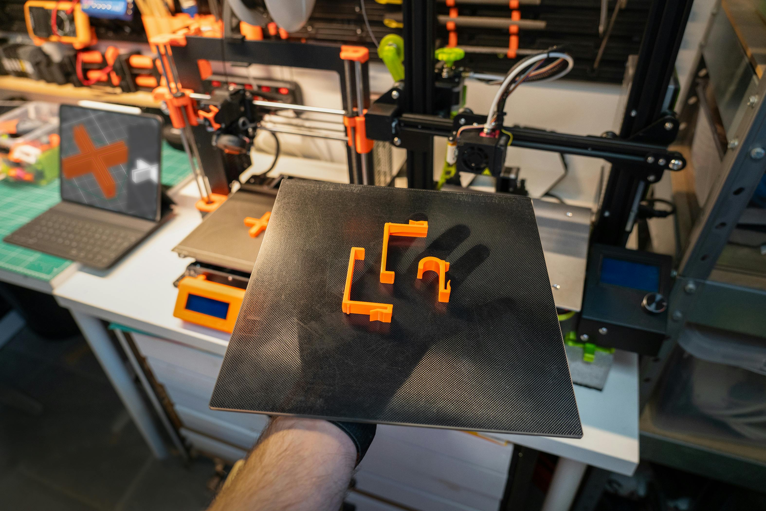
Hybrid Manufacturing
Integration of additive manufacturing (3D printing) with sheet metal fabrication is emerging, enabling complex hybrid parts.
Deep Dive: Advanced CAD Features Enhancing Sheet Metal Fabrication
While basic CAD functions like 2D drafting and simple 3D modeling are foundational, advanced CAD software offers powerful tools specifically tailored for sheet metal fabrication that further streamline the process and enhance manufacturability.
a. Parametric and Associative Design
Parametric modeling in CAD lets engineers define relationships between features—if one dimension changes, dependent features adjust automatically. This associative behavior is crucial in sheet metal, where changing thickness or bend radius impacts flat patterns and bend allowances.
For example, increasing flange length automatically recalculates bend reliefs and updates the flat layout. This dynamic updating minimizes redesign effort, especially when iterating through customer revisions.
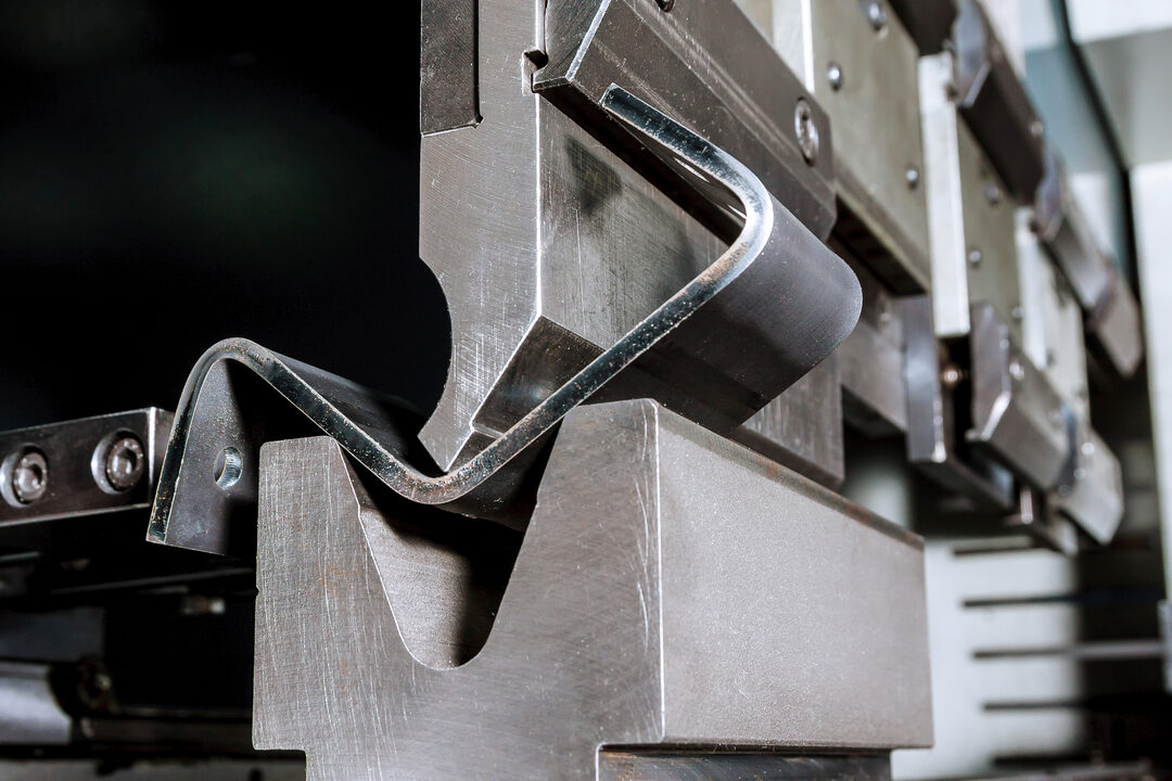
b. Bend Simulation and Springback Compensation
One of the biggest challenges in custom sheet metal fabrication is springback—the tendency of metal to partially return to its original shape after bending due to its natural elasticity. This phenomenon can lead to inaccuracies in the final part if not properly accounted for. Advanced CAD software packages help solve this issue by simulating springback behavior, allowing engineers to predict how much the metal will rebound. These tools automatically adjust bend angles and dimensions in the design phase, ensuring that the final fabricated part matches the intended specifications with high precision.
This simulation prevents costly trial-and-error during physical prototyping and ensures that the final bent part matches the intended design precisely.
c. Automatic Flat Pattern Generation and Unfolding
Creating accurate flat patterns is essential because these are what get sent to laser cutters or punch presses. CAD software automatically unfolds the 3D bent model into a flat layout, accounting for bend allowances and K-factors (a coefficient describing how material stretches).
The ability to export these flat patterns directly into CNC-compatible formats (like DXF) speeds up fabrication setup.
d. Design for Manufacturability (DFM) Checks
Some CAD platforms integrate DFM analysis tools that evaluate the design against manufacturing constraints, such as minimum bend radius, accessible tooling, and material limitations.
By flagging potential fabrication issues early, these tools help designers avoid costly redesigns and production delays.
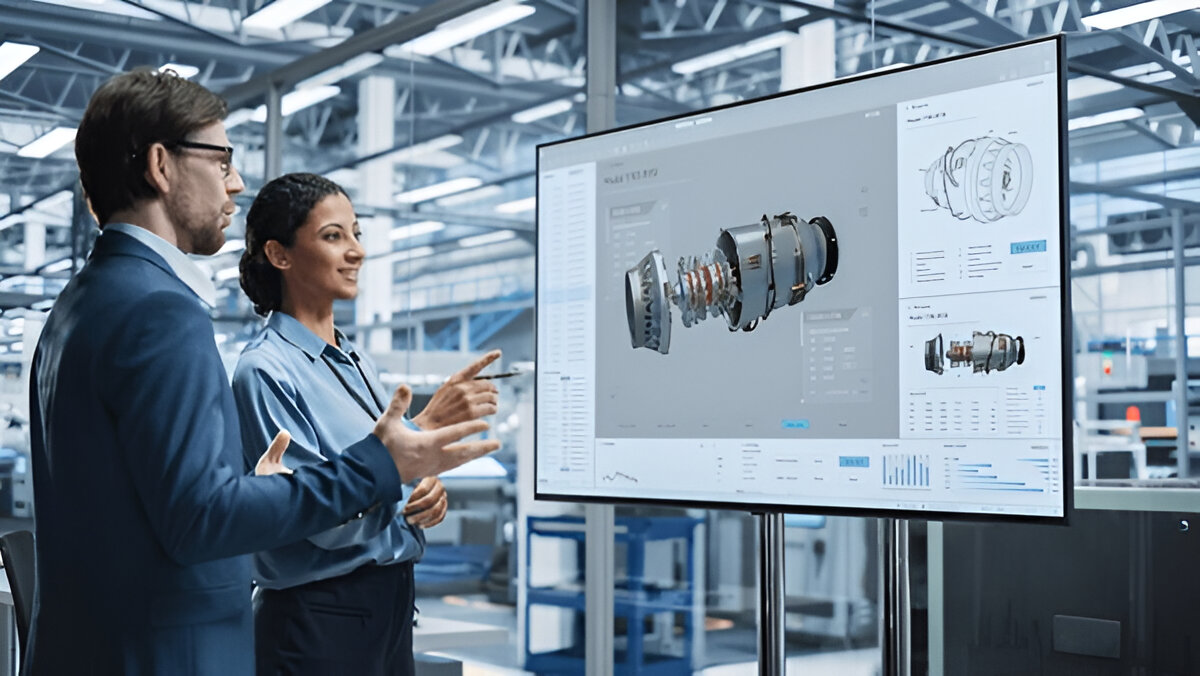
Collaborative Workflow Enhancements with CAD Software
The modern sheet metal fabrication process rarely happens in isolation. It requires coordination among design engineers, manufacturing specialists, quality control teams, and clients. CAD software has evolved to facilitate this collaboration:
Cloud-Based Platforms
Cloud-enabled CAD tools like Onshape or Fusion 360 allow multiple stakeholders to access, review, and modify designs simultaneously from anywhere in the world. This real-time collaboration shortens feedback loops and accelerates decision-making.
Version Control and Audit Trails
Managing multiple design revisions is a challenge in complex projects. Modern CAD systems include integrated version control, which tracks every change, records who made it, and allows rollbacks if needed. This ensures traceability and reduces confusion over which design version is current.
Annotation and Markup Tools
Collaborators can add comments, suggestions, and annotations directly on CAD models or drawings, simplifying communication and eliminating misinterpretations common with email or separate documents.
Real-World Industry Examples Highlighting CAD’s Impact
Aerospace Industry
In aerospace, where precision and safety are paramount, sheet metal parts like airframe panels and ducting are highly complex and must meet strict standards. CAD software allows engineers to design parts that optimize weight without sacrificing strength.
For example, Boeing and Airbus use CAD-driven workflows extensively to simulate stress points and bending behaviors in sheet metal parts, reducing prototype cycles and improving quality.
Automotive Sector
Automotive manufacturers rely on CAD to design thousands of custom sheet metal parts, from body panels to chassis brackets. CAD enables rapid prototyping and testing of aerodynamic shapes and crash impact zones using integrated simulation tools.
Tesla, for instance, uses advanced CAD software for its vehicle panels and structural components, allowing faster iteration and tighter integration with robotic manufacturing cells.
Electronics and Consumer Goods
Enclosures for electronics require precise cutouts, ventilation slots, and mounting points. CAD software helps designers optimize thermal management and ease of assembly.
Companies like Apple and Samsung leverage CAD to develop sleek, custom sheet metal casings for their products, ensuring tight tolerances and high-quality finishes.
Overcoming Common Challenges in CAD-Driven Sheet Metal Fabrication
Despite its advantages, adopting CAD software for sheet metal fabrication presents some challenges:
Training and Skill Development
High-end CAD systems are feature-rich but complex. Staff need training to use them effectively. Investing in continuous education and certification programs helps maximize ROI.
Data Interoperability
CAD and CAM systems from different vendors might use incompatible file formats, risking data loss or errors during transfer. Utilizing standard formats (STEP, IGES, DXF) and maintaining a centralized data management strategy mitigates this risk.
Hardware Requirements
Advanced CAD software can be resource-intensive, requiring powerful workstations and high-quality graphics cards. Ensuring IT infrastructure supports these demands is essential.
Keeping Up with Software Updates
Manufacturers must stay current with CAD software versions to leverage the latest features and security patches, which requires regular budgeting and planning.
The Future: How Emerging Technologies Will Shape CAD in Sheet Metal Fabrication
Artificial Intelligence (AI) and Machine Learning
AI is beginning to revolutionize CAD by automating routine tasks, suggesting design improvements based on manufacturing data, and predicting potential failure points before they happen.
AI-powered generative design tools can create multiple optimized design alternatives for sheet metal parts, balancing weight, strength, and cost.
Augmented Reality (AR) and Virtual Reality (VR)
AR and VR tools integrated with CAD models allow engineers and fabricators to visualize and interact with sheet metal parts in a 3D virtual space before manufacturing. This immersive experience enhances design reviews and assembly planning.
Digital Twins and IoT Integration
By linking CAD models with real-time sensor data from fabrication machinery (IoT), manufacturers can create digital twins — virtual replicas of physical parts and processes that monitor performance, predict maintenance needs, and optimize production.
Conclusion
CAD software has become the backbone of modern custom sheet metal fabrication. Its ability to create precise, optimized designs while seamlessly integrating with CAM and CNC processes enables manufacturers to meet complex demands efficiently and cost-effectively. As CAD technologies continue to evolve—embracing AI, cloud collaboration, and digital twin capabilities—the future of custom sheet metal fabrication promises even greater innovation, speed, and sustainability.
Whether you are a fabricator, engineer, or designer, mastering CAD software and its application in sheet metal fabrication is essential to staying competitive in today’s dynamic manufacturing landscape.