How CAD Software Is Revolutionizing Custom Sheet Metal Design and Fabrication
Introduction
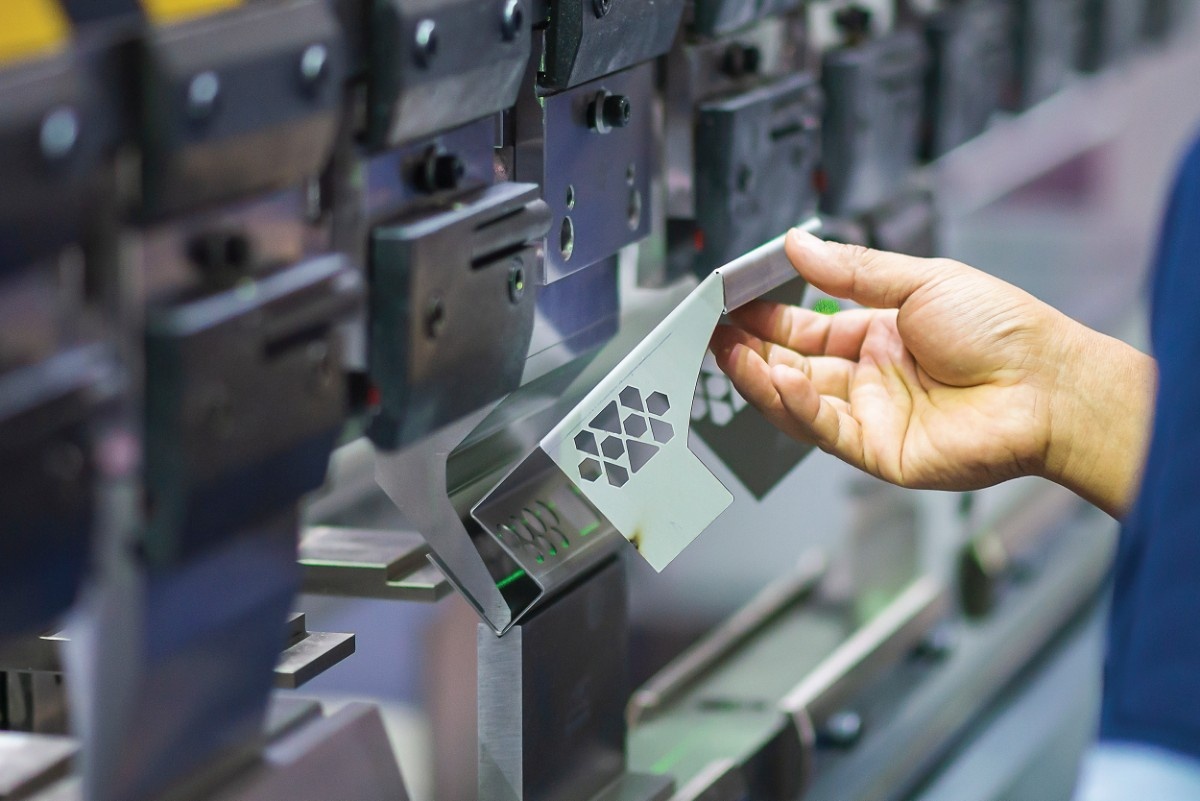
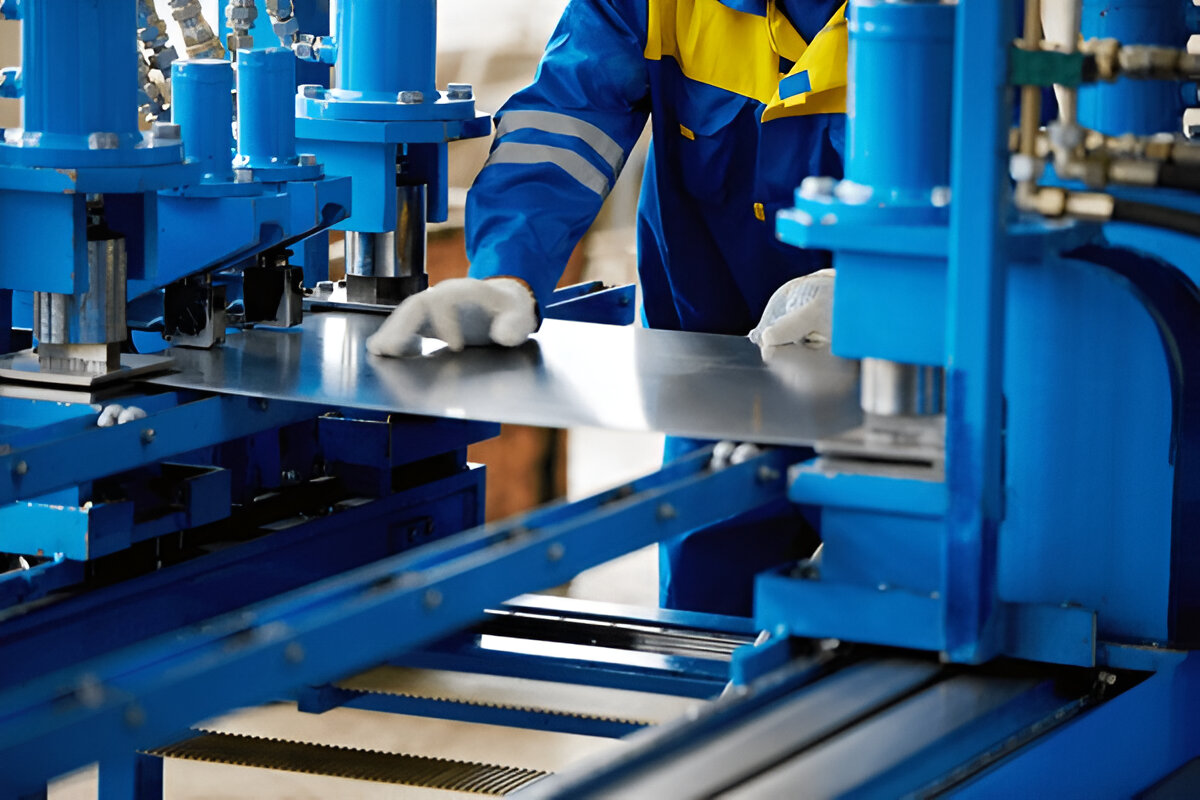
Sheet metal remains a backbone of modern manufacturing—found in everything from architectural façades to aerospace structures, medical devices to consumer electronics. Over the years, the industry has evolved toward more customized, intricate designs with tighter tolerances, responding to demands from sectors like automotive, renewable energy, and electronics. The rise of custom sheet metal fabrication has been meteoric: designers and clients increasingly require tailored solutions, embedded functionalities, and optimized designs, all needing rapid turnaround and high precision.
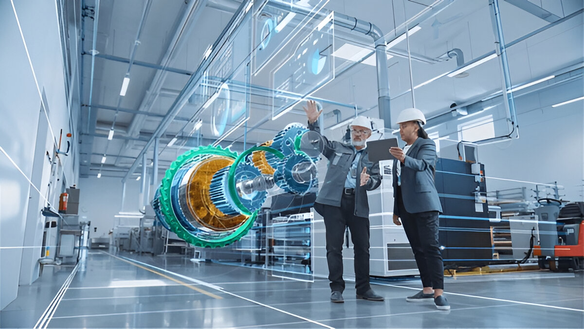
Meeting these demands relies not only on skilled craftsmanship, but also on the technological integration of design, validation, and manufacturing. Central to this shift is the adoption of advanced CAD software—solutions whose sheet‑metal modules, parametric engines, automation tools, and simulation capabilities have fundamentally altered how sheet metal fabrication manufacturers operate. From concept design to CNC-ready drawings, CAD workflows ensure seamless transitions between design intent and real-world manufacturing. When leveraged fully, they enable precision sheet metal fabrication, minimize costly errors, and foster innovation through generative design or AI assistance.
From 2D Drafting to Parametric, Feature‑Based CAD
The journey from traditional drafting boards and 2D CAD to today’s robust 3D parametric platforms—such as SolidWorks, Autodesk Inventor, Siemens NX, and PTC Creo—marks a paradigm shift. In parametric, feature‑based CAD, designers build a history tree composed of sketch-based features (cuts, flanges, bends, holes). Each feature is defined by functional dimensions and constraints. Modify any dimension (e.g., bend angle, flange width), and the entire model updates automatically—preserving design intent.
Benefits for Sheet‑Metal Workflows:
- Rapid Iteration: If material thickness or bend radii need adjustment, the flattened representation updates accordingly—eliminating hours spent recalculating patterns manually.
- Family Design & Configurators: Companies producing similar enclosures or brackets can use a single template, varying parameters like flange length, hole placement, or form feature inclusion to produce multiple variants.
- Embedded Manufacturing Intelligence: Smart CAD recognizes bend allowances and bend sequences, integrating them into the part’s metadata.
This parametric foundation elevates precision sheet metal fabrication, as every change cascades consistently—from form to function and manufacturability.
2. Sheet‑Metal–Specific CAD Functionality
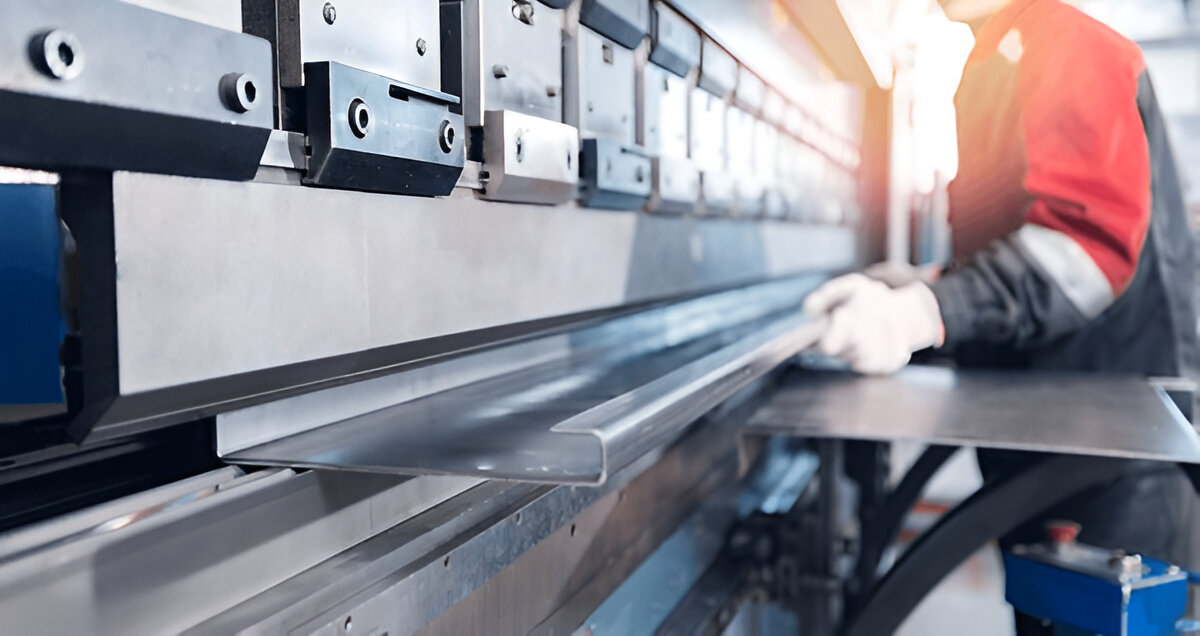
General 3D CAD tools are powerful, but sheet‑metal design raises unique challenges: controlling bend radii, stretch beyond reliefs, establishing flat pattern accuracy, managing bend sequence, and simplifying downstream path planning. This led to specialized modules and dedicated solutions like SolidWorks Sheet Metal, Autodesk Inventor’s Sheet‑Metal environment, and dedicated tools like Lantek Expert.
Key Capabilities:
- Auto‑bend Recognition & Reliefs: Fillets, louvers, tear‑drops, and U‑reliefs accommodate bending without tearing or deformation.
- Flat‑Pattern Generation: Auto‑unfolding produces CNC-ready DXF patterns, complete with bend lines, welded seams, and ANC configurations.
- Bend Tables: Adjustable based on material, gauge, or supplier; these tables feed into unfolding algorithms to match real-world punch press behavior.
- K-Factor & Bend Allowance Control: Critical for ensuring flat patterns reflect material spring‑back characteristics.
- Corner Treatments: Preset options like mechanical joint tabs, lances, hem edges, and stiffening beads.
- Complex Forms: Half‑shell enclosures, slotted connections, integrated fastener flanges—all modeled and unfolded accurately.
- Automatic Feature Propagation: Edits to a form feature replicate on unfolded and final bodies, ensuring consistency.
These specialized features help sheet metal fabrication manufacturers close the loop between digital design and physical execution, cutting trial‑and‑error and rework costs.
3. Design Automation, Configurators & AI‑Enhanced CAD
As customization scales, manual edits become time-consuming. CAD advances have responded with automation, scripting, and even AI‑assisted design.
Automation Paths:
- Macros & API Scripting: Teams use scripts (e.g. in VBA, Python) to automate repetitive tasks—like welding standoff placement or extracting bend table updates.
- Design Configurators: Web-based tools (e.g., built with Propel or DriveWorks for SolidWorks) let clients specify enclosure dimensions, hole sets, or finishes. CAD models and BOMs generate automatically.
- Knowledge-Based Engineering (KBE): Embedding manufacturing rules—like bend minimum radii or material thickness rules—enforces design standards.
- Generative Design & Topology Optimization: Software like Autodesk Fusion 360 or nTop enables topology‑aware lightweight structures. For sheet metal, this leads to organic perforation patterns, magnetic field‑aware airflow paths, or stiffness‑optimized stiffener shapes.
- AI‑Driven Parameter Estimation: Some emerging platforms can suggest bend radii or relief dimensions based on learned data from previous designs.
- Chat‑to‑CAD Interfaces: Cutting‑edge research is exploring ChatGPT‑style language interfaces where designers type “create 2 mm aluminum bracket, 50 × 80 mm, 4 mounting holes” and see a parametric model appear.
The result: custom sheet metal fabrication turns from manual labor into an efficient, software‑driven process—closely integrated with production realities.
CAD & CAM Integration: Nesting & CNC Export

After design, parts must be manufactured. CAD's true value manifests in its smooth hand‑off to CAM.
Toolchain Integration
- DXF/DWG flat pattern export: includes strategic markers, holes, form features.
- Direct integration with nesting tools: solutions like SigmaNEST, Lantek, or TruNest import straight from CAD with bend data intact.
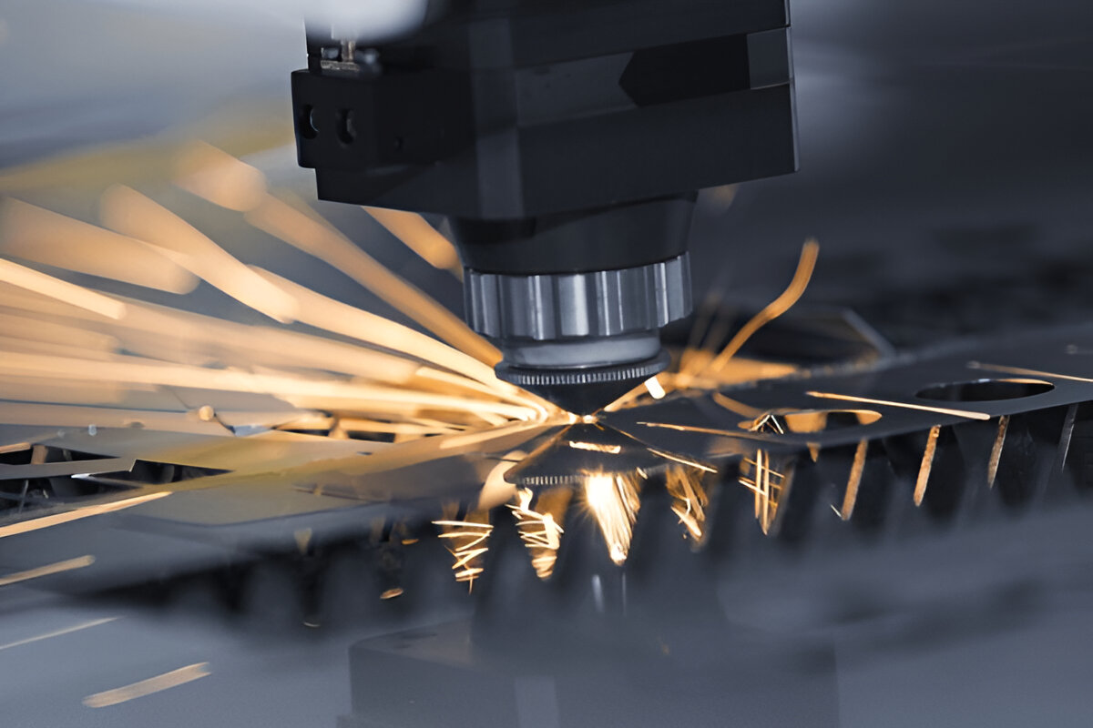
- Post processors for CNC punching, laser, water‑jet, or turrets.
- Robot Programming Outputs: For bending cells or welding stations, some CAD packages export toolpath instructions in KUKA or ABB formats.
Nested layouts maximize yield, considering part geometry, common bend lines, and cut paths. CNC controllers receive machine‑ready G‑code, ready for lights‑out production.
This integration is vital for precision sheet metal fabrication—everything from hole placement accuracy to controlled bend sequencing relies on tight CAD‑CAM linking.
Simulation & DFM (Design for Manufacturing) Validation
Before committing tooling or entering production, CAD models can—and should—undergo virtual validation:
- Collision & Bend‑Sequence Analysis: Detects if too many flanges collide during folding, or if tooling paths intersect.
- Finite Element Analysis (FEA): Thin‑sheet bending behavior and stresses can be simulated. Fault-prone areas—like corners under forming—can be reinforced preemptively.
- Manufacturability Checks (DFM): Software flags issues like too-tight embosses, undercutting stepdown limits, or inaccurate weld‑length path deviations.
- Spring‑back Compensation: Simulating each bend cycle allows compensatory offsetting, critical for materials like stainless or Inconel.
- Thermal & Vibration Simulation: For enclosures or electronics housings, CAD may simulate heat transfer and structural loads.
Virtual validation means fewer prototype runs, shorter lead times, and better-quality custom sheet metal fabrication.
Real-Time Collaboration & Cloud-Based Workflows
Once siloed on local drives, CAD has moved to the cloud—via PDM and data collaboration platforms like Autodesk Fusion Team, Siemens Teamcenter, or Dassault ENOVIA.
Core Features:
- Version Control: Track design iterations, revert changes, audit trail.
- Browser-Based Viewers: Enables clients, contractors, integrators to inspect models without installing CAD.
- BOM & Manufacturing Doc Integration: Automatic extraction of material lists, thicknesses, finishes, and annotations for punches or welds.
- Co-Editing: Multiple users can comment, suggest, or modify—in real time.
- RFQ & Quoting Portals: Integrated with ERP—auto-generated flat patterns and BOM tables feed into pricing engines for rapid quoting.
These systems bridge the gaps between designers, sheet metal fabrication manufacturers, welders, and clients—creating a unified digital thread.
Industry Case Studies
Case Study A: Aerospace Bracket – Boeing
A major aerospace OEM transitioned to Autodesk Inventor with specialized FEA plugins. They modeled up to 350 fabricated brackets, automating bend reliefs and using nesting tools to route .025" Inconel edges. Virtual simulation flagged critical deflection points under cyclical loads—leading to design revisions without any physical prototypes. Result: 35% weight reduction and 20% manufacturing time savings.
Case Study B: Medical Sterilizer Housing – SteriTech
Working in stainless steel with high hygiene standards, SteriTech used generative perforation patterns—solving airflow optimization and aesthetics simultaneously. The CAD-CAM chain produced vented enclosures with integrated locking tabs—fully built and bent within 12 hours of quotation request.
Case Study C: Industrial Enclosures – Eaton Electrical
Eaton’s switchgear panels, built from 1.5 mm Al-Mg sheets, were designed and quoted using a DriveWorks-driven config portal. Clients input voltages and port layouts; CAD generated flat-pattern DXFs, BOMs, bend tables, and nest-ready outputs automatically. Fabrication time dropped 60%; quoting responded within hours.
Quantifying the ROI
Embracing CAD‑driven workflows has real, recordable impacts:
- Time to Market: 30–70% quicker from concept to production-ready model.
- First-Time Quality: Prototype runs minimized—errors reduced 40–60%.
- Material Yield: Yield bump of 5–15% through improved nesting and pattern accuracy.
- Labor Cost Reduction: Fewer manual corrections, rework, and press stops.
- Design Reuse: Template and family-based design cuts development hours drastically.
- Better Customer Experience: Faster quoting and governance of design options.
These metrics are powerful justifications for investing in CAD systems and training across sheet metal fabrication manufacturers.
The Future: AI, Digital Twins, and IoT Feedback
Technology seldom sits still. Emerging trends promise further revolution:
Generative & AI‑Driven Design
CAD systems are beginning to propose optimal bend lines, perforation patterns, or configuration variations. Generative systems learn from past jobs, fabricators’ feedback, and defect data—creating improved performance variants.
Digital Twins & IoT Integration
In high-complexity environments (e.g., oil & gas enclosures), panel welders or robots embed IoT sensors. Operational data feeds back into design modules—enabling live parts to guide future tolerance or material updates.
Multi‑Material & Additive Hybrid Workflows
Combining sheet metal with 3D-printed inserts, cast brackets, or engineered living hinges leads to hybrid fabrication. CAD platforms adapt to tooling chains that combine punching, folding, and additive processes within one workflow.
Natural Language Options
Pilot projects are enabling voice or text-based CAD generation—such as “Draw a 1.2 mm aluminum bracket, 80 × 40 mm, with flanges at 90° and hooks on each corner” – producing editable 3D model as output.
Low-Code Automation Extensions
Web-based config portals evolve into rule‑driven parts factories. Administrators define feature‑sets and customization rules—allowing for rapid deployment across teams or even reseller channels
Overcoming Challenges & Best Practices
Despite its potential, deployment isn’t friction-free. Manufacturers and designers must consider:
- Skill Gaps: Moving from 2D to parametric tools requires training. CAD skills are no longer optional.
- Standardization of Bend Tables & Material Properties: Inconsistent data leads to flattening errors. Collaboration across sourcing and fabrication teams matters.
- Data Management: Large assemblies, sheet‑metal weldment robots, nesting directories—proper PDM is essential.
- Cross‑Discipline Collaboration: Mechanical, electrical, and layout teams must share design environments.
- Incremental Rollout: Begin with pilot projects (e.g. enclosures or bracket families) to establish ROI before scaling full‑floor adoption.
Applied thoughtfully, these best practices will help custom sheet metal fabrication leaders accelerate digital transformation.
Perspectives from Industry Leaders
“Using sheet‑metal tooling automation, we’ve cut engineering hours by over half. Projects that once took three days now finish in one,” says Peter Liu, Engineering Manager at Mercury Cabinets (a precision sheet metal firm).
“Our ERP/PDM‑linked quoting system pulls design data straight from CAD. Turnaround used to be 72 hours; now clients get priced options within hours,” remarks Anita Evans, CTO at Fabricatech Inc.
Note the recurrence: alignment between CAD design, manufacturing constraints, and customer communication is at the core of next‑gen fabrication.
Industry-Specific Adoption of CAD in Sheet Metal Fabrication
Electronics & Enclosure Manufacturing
In electronics, enclosures must be compact, EMI-shielded, thermally efficient, and often meet regulatory standards such as IP ratings or UL listings. CAD software helps engineers integrate cable routing, component spacing, and airflow paths into a single design environment. Precise alignment of standoff mounts, cutouts, and bend clearances ensures that housings match PCB layouts perfectly—often down to the millimeter.
For instance, CAD-integrated libraries enable automatic placement of standard components like card guides, fasteners, or louvers. When incorporated into configurators, these templates let OEMs create thousands of custom variations for server racks or telecom cabinets—each designed, validated, and prepped for manufacture in hours, not days.
Automotive & EV Sector
In automotive manufacturing—especially with electric vehicles (EVs)—sheet metal parts must meet structural strength standards while minimizing weight. CAD tools enable designers to perform topology optimization for crash rails, battery enclosures, or mounting brackets. Combining this with materials science data and crash simulation, OEMs can ensure strength-to-weight ratios are optimized before building physical prototypes.
AI-powered CAD also facilitates the integration of multi-material components (e.g., steel for structure, aluminum for weight reduction), which require different bend parameters and manufacturing processes.
Construction & HVAC
Architectural sheet metal—used in ducting, decorative panels, or weatherproof façades—must conform to building standards and site-specific layouts. CAD software allows designers to create parametric, building-integrated forms that auto-adjust based on wall dimensions, floor heights, or duct routing constraints. These models directly export to CAM for turret punches or press brakes, allowing sheet metal fabrication manufacturers to deliver accurate parts to job sites—pre-labeled and ready to assemble.
Sustainability Through Digital Design
CAD’s contribution to sustainability in custom sheet metal fabrication is significant—yet often overlooked.
Material Optimization
Through nesting algorithms and generative design, CAD ensures every sheet of metal is used efficiently. Nesting software can increase material yield by up to 20% compared to manual layout planning, reducing both raw material costs and scrap sent to landfills.
Paperless Workflows
Digitally connected CAD-to-CAM systems eliminate printed drawings, manual markup sheets, or duplicated order forms. Shop-floor tablets or monitors receive live part data, BOMs, and bend charts directly from the CAD environment—minimizing waste and documentation errors.
Reduced Rework
Simulating thermal behavior, load paths, or tolerance stack-ups reduces trial-and-error runs, scrap parts, and wasted man-hours. A part that’s right the first time is inherently more sustainable.
Lifecycle Modeling
CAD also plays a role in the product lifecycle: from energy modeling in enclosures to lifecycle analysis (LCA) integrations, designers can make choices that lower carbon footprints over the full life of a fabricated component.
Design for Disassembly
By modeling joints and fasteners that simplify disassembly, products designed in CAD can be easier to repair or recycle—promoting circular manufacturing.
The Workforce Shift: Upskilling with CAD
As CAD becomes central to precision sheet metal fabrication, workforce expectations are evolving.
From Draftsman to Digital Designer
The modern sheet metal designer is not just drawing parts—they're programming logic into intelligent models, ensuring manufacturability, and driving automation. Knowledge of parametric modeling, simulation, and CAM integration is now essential for junior and senior designers alike.
Machine Operators as Digital Interpreters
Operators on the floor increasingly engage with CAD-derived outputs. CNC bending machines or turret presses require operators to interpret digital bend sequences, DXF layouts, or form tolerances. Training in CAD viewers and ERP-linked software helps bridge the gap between digital design and physical manufacturing.
Cross-Functional Teams
Designers now work alongside procurement, quoting, and sales teams who rely on CAD data for BOM generation, quoting, and lead-time forecasting. This multi-disciplinary integration demands new collaboration tools—and new soft skills.
Apprenticeships and CAD Training
Forward-looking sheet metal fabrication manufacturers are partnering with technical schools and online platforms to offer training in tools like SolidWorks, Fusion 360, and Inventor. Apprenticeships now blend hands-on fabrication training with parametric design, CAM preparation, and basic scripting.
Democratization via No-Code Tools
Some vendors are introducing visual programming and no-code CAD platforms—making automation accessible even to non-engineers. Fabricators can build templates, rule sets, or quoting tools without writing complex code, unlocking new efficiencies and empowering small teams.
What’s Next? CAD and the Fabrication Landscape in 2030
Looking ahead, the trajectory for CAD in sheet metal fabrication is deeply tied to broader shifts in manufacturing:
- Hyper-Personalization: Expect clients to design their own enclosures, racks, or brackets through web-based portals tied directly to CAD back-ends.
- Autonomous Factories: CAD models will feed directly into automated bending cells, robotic welders, and laser cutters—requiring no manual intervention between approval and production.
- Real-Time Costing: CAD models will carry embedded cost metadata (material, machine time, finish, labor), enabling instant quoting at the design stage.
- Eco-Feedback Loops: Integration with carbon calculators and sustainability dashboards will influence design choices based on environmental impact in real time.
- Global Collaboration: Distributed teams, freelancers, or clients across borders will co-design in shared CAD environments—enabled by cloud-native platforms.
Conclusion
CAD software has come a long way from the era of static blueprints and paper-based drafting. It has evolved into a digital powerhouse that orchestrates every phase of the manufacturing pipeline—from initial design concepts and performance analysis to real-time quoting, simulation, and final fabrication. For today’s sheet metal fabrication manufacturers, CAD is no longer just a design aid—it’s the strategic core of operational efficiency and innovation.
One of the most transformative outcomes of modern CAD tools is the ability to deliver truly custom sheet metal fabrication at scale. Whether a client requires a uniquely shaped bracket, a tailored electrical enclosure, or a specialized ductwork layout, today’s CAD platforms empower designers to create, simulate, and validate intricate components with remarkable speed. This high level of customization is no longer limited to low-volume or prototype work—it’s now achievable even in high-throughput production environments. More importantly, CAD ensures these designs adhere to the tight tolerances and quality standards essential in precision sheet metal fabrication. Manufacturers can meet exacting customer specifications without sacrificing speed, cost-efficiency, or consistency. As a result, personalization and productivity no longer conflict—they complement each other, driven by intelligent, CAD-enabled workflows.